NEW HARDWARE DEVELOPMENTS
Super Game Module / 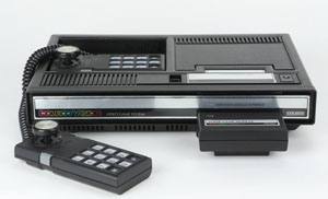 Super Expansion Module, by Opcode games (releasedate: 2012/2013)
-Increases ColecoVision RAM memory from 1KB to 32KB
-Doubles the ColecoVision and ADAM sound capabilities
-Adds a power LED to the ColecoVision
-Compatible with both the ColecoVision and ADAM
-Uses a custom plastic case based on classic Coleco design
-Comes with professionally printed box, manual and catalogs. Packaging mimics the classic ColecoVision packaging design circa 1982/83, so it will match your ColecoVision collection nicely.
-Officially licensed Coleco product
When a game requires Opcode's SGM to run, a special label is drawn somewhere on the game box.
Memory pack, by Opcode games (releasedate: 2006)
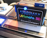 The Colecovision Ultimate SD Cartridge, by Atarimax
The Ultimate SD includes a 50 MIPS onboard CPU, advanced upgradable hardware logic, 512KB of SRAM and 128KB of block flash. The Ultimate SD Cartridge supports the following Colecovision ROM formats:
-All standard 32K or less ROM images.
-MEGA-CART Bank-switched ROM images up to 512KB (Mario Bros, Pac-Man Collection, etc)
-Lord of the Dungeon (Including NVRAM with automatic save to SD card!)
-New modes including the Hybrid 512KB full Read/Write 8k/8k Bank-switching mode
The Colecovision 128-in-1 USB Cartridge, by Atarimax
-Supports standard Colecovision ROM Images up to 32K.
-While this covers most of the ROM images produced for the Colecovision, it does not cover a few new homebrew games like Pac-Man Collection and Mario Brothers, which require the Mega-Cart bank switching scheme.
-Does not support Lord of the Dungeon.
Multi-console adapter, by Richard Hutchinson (beta-stage)
Colecovision Retrobox, by Retrozone
The Retrobox is a small adapter for original Colecovision controllers, including the Super Action Controller.
Colecovision RAM Cart, by Kevin Horton
This cart was used to test games on the console. It was never released to the public.
Colecovision multicart, by Kevin Horton
The multicart was only developed as a prototype and was never released to the public.
Colecovision serial-communication, by Jeff Frohwein
SEPARATE AUDIO/VIDEO HACK BY SEAN KELLY
(The following is a modification which can be used to improve your ColecoVision. The authors of this list and this modification can not be responsible for any damage done to your unit or person as a result of attempting this modification.)
This is a rather feeble attempt at describing the hack to the ColecoVision video game system to give separate audio and video outputs to the system. I am what I call an "Electronics Tinkerer" meaning I have no formal education in electronics and basically only know what I have been able to figure out by ripping apart everything I own !
I am a collector of Classic video games and systems and ran across this hack on one of the many ColecoVision systems I own. It actually works quite well and gives the on- screen images a much crisper look to them. Audio is generally pretty poor on the ColecoVision and this hack doesn't do much to help it.
In order to get things started you have to open up the ColecoVision by removing the 8 screws on the bottom of the case. With the screws removed, the case is still something of a pain to open because of the lip on the expansion port, but just keep working at it and it will eventually come apart. Next thing is to remove the screws holding down the motherboard itself (three of them I believe) and take the motherboard out of the case. On some versions of the ColecoVision the aluminum cover is soldered to the circuit board. If this is the case on yours, you will have to desolder it and remove both the top and bottom parts to the aluminum cover. Set everything but the motherboard aside and you are ready to get to work.
The person that did the hack on this system uses a small automotive-type fuse block terminal to mount the components of the circuit board on. I have located it in the 1992 Radio Shack catalog (page 150) and it is RS part #274-688. It comes in a package of four for $1.29. Here is a list of the components used: AGAIN - I have no formal electronics education and don't really know how to read all the weird symbols on the parts. I will do my best to describe them (I have also labeled them on the line below for future reference - take note):
                  Transistor

                  (T1)
                  -

                  No part # markings at all.  Only thing on it is a white, red, and green stripe in that order from top to bottom.  I assume this tells what kind/type it is?


                  POSSIBLE (!) RS Part #276-1617   $1.98 (pkg. of 2)


                  Capacitor

                  (C1)
                  -

                  Electrolytic type with  part #N8408 on it.  It also has the marking "470uf 35v", but the "u" is one of the funny symbols that I have no idea what it means.


                  RS Part #272-1030    $ .99


                  Capacitor

                  (C2)
                  -


                  Ceramic Disc type.  Only marking on it is an underlined "47".


                  RS Part #272-121   $ .39 (pkg. of 2)


                  Resistor

                  (R1)
                  -


                  I know these are defined by the colored stripes (See - I'm not a complete idiot!!  haha).  The stripes are: Orange, Orange, Brown, and Gold.


                  A/V Cable
                  -
                  One Audio/Video cable with the RCA plugs cut off on one end.
You will also need about 5 small pieces of wire around 4" long each.
We're looking at a total of about five bucks to do this so for parts that do not come in packages of two or more, I would suggest buying an extra one, unless you know what you're doing, in case you screw something up.
The center connector on your terminal will be the ground for all the components because it is the only terminal that sticks out on both sides of the block. The part the extends on the bottom will be used to mount to terminal to the ColecoVision motherboard. Directly to the right of the RF modulator (big silver box on the motherboard) right under the letter of the revision of the motherboard (the one I am looking at is "J") you will have to scrape off a section of the green coating so you can solder the terminal on the bottom to the motherboard. After soldering this bend the terminal block so that it is standing straight up from the motherboard.
Since many of the components will be "tied" together, you might want to connect them all to the posts first and then solder them later. The way I am going to describe how to connect them will (hopefully) make it as easy as possible to understand. The following is a listing of each post numbered from 1-5, left to right, looking at the terminal block from the back of the motherboard. Looking at the "back" you will be looking at the channel 3- 4 switch as well as the RCA plug that is used to connect the ColecoVision to the TV/Game switch now. Here is what goes on each post:
                  Post #1


                  -


                  The LEFT "leg" of the transistor.  I am looking at the transistor on the side that is curved - where you can see the color bands.


                  One of the small pieces of wire goes from this post to the right leg of the disc capacitor on the ColecoVision motherboard itself marked "C22".


                  Post #2
                  -
                  The CENTER "leg" of the transistor.


                  One "leg" from the Disc capacitor.


                  One of the small pieces of wire goes from this post to the underside of the ColecoVision motherboard.  It will be EXTREMELY hard for me to explain where to connect this on the bottom of the motherboard since there are no markings on this side.  The only way I can describe it is to say that it is being connected to one of the components in the RF modulator.  The RF modulator is "outlined" in a sense on the bottom of the MB with solder because of grounding.  You need to connect it to the pin that has the marking "+12" at about 5 O'Clock.  This is the closest pin to he "+12" marking.


                  Post #3
                  -
                  This is the GROUND post.  One side of the resistor is connected here.


                  The two ground wires from the RCA cables must be connected here also.  Each Audio/Video wire has two wires inside of it.  In general, one is shielded in plastic and the other is not.  The unshielded wire is the ground.  Connect the unshielded wire from each cable to this post.


                  Post #4
                  -
                  The side of the Electrolytic capacitor (C1) that the arrow printed on the capacitor points to.


                  This is where I am sort of unable to help you.  The positive wire from the Audio or Video wire needs to be connected to this post.  Since the RCA ends are cut off the cable I don't know which is which.  It should not damage anything by connecting them the wrong way, so you will have to take a guess.  One of them goes on this post and the other goes on post #5.


                  Post #5
                  -
                  The other of the positive Audio/Video wires gets connected here.


                  One of the small pieces of wire goes here.  This one is even harder to describe than the one on post 2.  The "outline" in solder around where the RF modulator is mounted on the opposite side is where you are going to connect this wire.  Looking at the bottom of the MB with the expansion port facing you the part of the "outline" you need to connect this wire to will be on your left.  It's  small section of solder (compared to the section on the right) and is about 1.5-2 inches long.  Connect this wire anyplace here.
You now have one leg of the transistor (T1), one leg of the resistor (R1), and one leg of each capacitor just hanging there right? Connect all of these together, but do not connect them to any of the posts. Just sort of let them hang there.
The person who did this to my system also has one other wire connected to the bottom of the motherboard, but the other end of it has been cut and is not connected to anything. I assume this serves no purpose.
AUTOMATIC RF SWITCH
Creating an automatic RF switch (similar to that found on the NES and Super Nintendo) is relatively simple. Just add a 220-330 ohm 1/2W resistor from 12V thru a 180uh inductor to the center terminal on the modulator's output. The resistor limits the current in case the cable gets shorted, and the inductor keeps the RF out of the power supply, and interference out of the signal. The inductor size isn't too critical; anything from 80uh- 330uh should do the trick. - 39
Alternatively, a 47 ohm resistor can be used; a 100pf DC blocking capactior is also recommended. - 29
REPLACING THE COLECOVISION ROM
This procedure can be used either to replace a bad ROM, or to install a custom programmed EPROM.
Parts needed:
28 pin IC socket 2764 EPROM chip programmed with the COLECO.BIN file
Two short pieces of wire Soldering iron, solder, desoldering iron, etc.
(Note: If you haven't opened your ColecoVision before, you may have to use the desoldering iron to suck up some solder so that you can open up the RF shield and get to the circuit board. Also, you may want to consider repairing your power switch. Desolder it, take it apart, clean it, pack it with "dielectric grease" from an auto supply store, reassemble it, then resolder it.)
1) Desolder the old ROM chip. (U2) If you haven't desoldered chips before, get some practice or buy a pizza and split it with a friend who has. (See end of this section for tips on how to desolder an IC chip.) Also suck the solder out of the four extra holes, and out of the holes marked "WJ4" and "WJ5".
2) Insert the 28 pin socket into the holes and solder it down. Test your work by putting the ROM chip back in and turning the unit on. If the "COLECOVISION" screen comes up, everything is okay.
3) Solder short pieces of wire into the WJ4 and WJ5 holes.
4) On the underside of the circuit board are two small "bumps" in two short traces coming from the WJ5 holes. Cut the traces. Do NOT cut the long trace that ends in a "Y" next to a WJ5 hole.
5) Program a 2764 EPROM with the contents of COLECO.BIN, which can be found with the ColecoVision emulator.
6) Put the 2764 EPROM into the socket and test everything by turning on the unit and checking for the "COLECOVISION" screen. Now you're done!
Hints for desoldering:
* I use a Radio Shack desoldering iron. This has a red rubber bulb on it and a hollow tip. It's cheap and works well.
* Use a fresh tip for important projects! It's not worth trying to save two bucks only to ruin a circuit board or a chip. Tinning your tip is a good idea, too.
* Wait for the joint to completely melt before sucking out the solder. If you suck too soon, you may not be able to melt the joint properly any more. Wait about four seconds, or five for the four "corner" pins.
* When you have sucked out the solder from all of the holes, push all the pins to "crack" them off of the remaining solder.
* If you have done everything right, the chip should practically fall out of the board. - 29
COPYING COLECOVISION CARTRIDGES
Some ingenious hackers figured out a way to copy the ADAM Computer's Super Data Packs to blank cartridges that then can be used on the ColecoVision. Most of the ADAM Super Data Packs were duplicates of ColecoVision Cartridges, but contained an extra screen or other extras the cartridge version lacked. - JC
FWIW, I've now seen both a Super Donkey Kong and Super Donkey Kong Junior cart. The only extras I saw in Super DK Jr. were music during the level selection, and a fourth screen, but Super Donkey Kong adds some end-of- screen graphics (the carry-away after screen 1 and falling girders after screen 2) in addition to its fourth screen. - JH
Note that copying cartridges or software is a violation of copyright law unless permission to do so has been received from the rights holder.
Also note that pirated and reproduction cartridges for ColecoVision do exist. Some dealers sell them; some refuse to. Not surprisingly, pirated cartridges are considered to have very little collectible value, so be aware that they exist - particularly if you run across demo carts and/or extremely rare titles.
REPAIR TIPS
The following are suggestions for solving problems with your ColecoVision. The authors of this list and these tips can not be responsible for any damage done to your unit or carts as a result of attempting these fixes.
To fix a rolling picture/video problems:
The problem is with the power switch. You'll notice that if you were to jiggle it a little without turning the system off that it will make a complete mess of your screen. What I suggest is that you desolder the power switch from the circuit board, take the metal cover off of it and clean all the contacts and re-grease them after cleaning them. Make sure the metal cover is REALLY TIGHT when you put it back on though. From then on if you are very careful when turning the unit on/off it should work OK for you.
If you still have a problem go to an electronics store... and get a similar switch and replace it. Nothing else you can do really. - 05
Sorry if this is stating the obvious, but you seem to have a combination of an intermittent open and a heat sensitive component.
Get a can of "cold spray" made for isolating thermal intermittents: should be a couple of bucks at a local electronics shop. If you can get the box open and get to all the components, it should be fairly straightforward to figure out which one is the bad guy.
Actually, by your description (starts good, goes bad after 2 minutes, can be affected mechanically) leans towards a bad solder connection (or socket it the darn thing has them). It may be as easy as touching up a few solder connections. - 06
If the video problem is simply vertical lines dragging behind the sprites, it can sometimes be solved by using a different power supply. - 16
A number of problems (warping sprites, lack of audio, lines in sprites, etc.) can, in many circumstances, be solved simply by assuring a solid connection between the power supply and unit. This can require hardwiring the power supply to the unit. - 33
In some cases, sprite problems can be solved by cleaning the cartridge in question. But if the startup screen has letters screwed up, such as CKHACK, you probably have a bad DRAM. U10 is D7 and U17 is D0. CKHACK indicates a bad D2 line, which would be U15. General directions for replacing a bad chip can be found in Section 10.3. - 29
To avoid an automatic level select problem:
One common ColecoVision trouble is that the controller ports break down easily, causing symptoms such as the ColecoVision thinking the keypad is constantly being pressed (which can cause the a game to be automatically started, as the level select is essentially instantaneous). A frequent source for this problem is the high sensitivity to static electricity which the controller port pins exhibit. To avoid the problem, simply don't touch the controller port pins unless properly grounded. - 08
To fix an automatic level select problem:
One possible piece which can be blown by static electricity at the controller ports (see 10.2) is the SN74LS541N chip, a 3-to-8 decoder. If this is the chip that's blown, then replacing this chip (a generic component, available at any good electronics store) can solve the problem. - 13, 15
Parts:
A good soldering iron (with a very thin tip)
Computer solder (thin)
Solder wick
Needle nose pliers
An SN74LS541N chip
Two 2.2K K27 resistor packets (optional/recommended)
Getting started:
Plug in and turn on the Coleco with a Donkey Kong cart inserted. When the game automatically goes into play mode, note if the Mario moves without touching the joystick. If so, then the 1st player chip is defini tely damaged. If a two player game is the one automatically started (which seems to be the prevalent fail mode) automatic movement of the second player's Mario likewise indicates that the 2nd player chip is certainly damaged. Lack of automatic movement does not rule out the possibility that either or both chips are damaged; indeed, given the automatic select problem, it's likely that at least one chip is damaged. But determining that one chip is certainly damaged can minimize your work.
Surgery:
1) Turn off and unplug your ColecoVision, removing the cartridge.
2) Make certain that you are properly grounded, if possible.
3) Open the plastic casing for the unit.
4) Remove the metal cover from the board by desoldering it. It just gets in the way so its better to remove it. It is not essential to the working of the game, though it can be resoldered later if desired.
5) the bare board upside down and find the soldering connections for the SN74LS541N chip that you wish to replace.
6) Note the orientation of the SN74LS541N you intend to replace, so that you can be certain that you provide the same orientation for the replacement chip.
7) Take the soldering iron and solder wick. Place the wick on one of the solder connections on the board. Press the solder iron on the wick. The iron will heat up the wick which will heat up the solder. The solder will turn liquid and be absorbed by the wick. This takes some practice before you get the hang of it.
8) Absorb as much of the solder as possible from all of the connections to the chip you're removing as possible.
9) Flip the board back over and take the pliers. This is where you have to get tough with your Coleco, and let it know who's boss! Growl at it occasionally to let off steam. Now, being careful not to harm any other components on the board, grip the defective chip with the pliers and pull and pry. It's OK to break the chip because it's defective garbage anyway.
*** Note - it's a good idea to wiffle each of the pins to pop them off any remaining solder. In fact, if the chip really is dead, it's better to just snip or Dremel all the pins off first, _then_ desolder the pins individually. - 29
10) After forcibly removing bits of the defective chip from the board, remove any broken pins stuck in the board, extra solder, etc. so that the area that was occupied by that chip is clean. Suck up the solder from the pinholes with the wick so that you can see right through the board through each pinhole. Gee, your ColecoVision never looked better!
11) Take the new SN74LS541N chip and gently install it in the board, inserting the pins in the pinholes. Make sure that the chip is oriented in the same direction that the original chip was! Gently bend the pins if necessary so that they all go in the holes. Be careful not to press too hard as you might bend some pins that aren't properly aligned with their holes.
12) Flip the board over. Take the solder iron and the computer solder and solder each connection carefully. Isn't this fun? Don't you feel like a computer technician now? :)
13) Optional/recommended: Replace the resistor packets on the port in a similar (though much easier) manner. For these parts, note the DOT orientation when replacing.
14) Put the board back in the plastic case to avoid shock.
To fix a broken roller controller:
When a roller controller will not register movement in one pair of directions (up-down or right-left), the problem might be with the infrared motion detectors. The pair of sensors appropriate to the direction simply need to be replaced with new off the shelf send and receive sensors.
Jumping and contact problems can usually be traced to the bearings. Sometimes these problems can be solved by cleaning the bearings; often, however, the problem can not be solved. - 11, 14
To fix a poorly responding controller:
A simple cleaning with a can of compressed air and TV tuner cleaner can greatly improve the responsiveness of the standard controllers.
To fix a dead cartridge:
Most cartridge problems are a result of bad (or no) contact between the cartridge and the system. Cleaning the cartridge and system contacts with alcohol usually solves the problem. As a last resort, a pencil eraser can be used on the contacts of the cartridge. - JH

